| Author | Message | ||
| Duane Pfeiffer |
I've been restoring a 2165 and I'm now stumped as to what is wrong. The problem is the volume is way too low until I turn the gain knob all the way up, then it jumps to full volume. I have replaced the output xfmr, replaced all the electrolytics accept a few that check out ok with my esr meter. (2uf) I've replaced all the op-amps with TL072s. I've replaced the JE1692s with 2N6488Gs. Replaced the Gain pot. Checked the tubes with tube checker. Replaced IC3 and IC7 sockets. Readings (low/high) 6L6 pin 3: 500/669 6L6 pin 4: 250/369 6L6 pin 5: 16/16 TR1: 1.1V IC7: pins 1,2,6,7 all nothing. Voltage across opamp pins 8 and 4 is 26V There is also a "knee" in the volume knob with a scope attached to C24 or C25 coming from IC7 pins 1 and 7. What I'm seeing is at about 3 or 4 the sine wave turns to a complete blur. thanks for any help you can provide! | ||
| Mike Kaus (mm210) Username: mm210 Registered: 05-2006 |
I guess first, I have to ask if this was blown up and a repair or if it was a "mod" thing or maintenence. Did it exhibit these symptoms before the work? Did you do this alittle at a time and at what point did it start? I guess I mean that you should track back to the cause, if it was. If not, it sounds like a shotgun approach. Not being a jerk here, just want to be able to help, if possible. Mike. | ||
| Lars Verholt (lmv) Username: lmv Registered: 11-2009 |
Is the issue the same on both input 'channels'? 16V on pin 5 is a bit low. Is your 22V bias supply checking out ok? I'm thinking your issue is either in the distortion 'clamp' circuit (which you could disable as a test) or your bias supply for the 6L6 tubes that makes the amp 'open up' if you drive the hell out of the preceeding stage. -Lars Verholt www.captain-foldback.com | ||
| Duane Pfeiffer |
I've been busy with other projects.... and this one is just too frustrating. I really want to get this amp working. I have resolved the 'knee' problem by installing LM1458s. However, no matter what I try, the amp won't 'turn on' until the gain is all the way up. The problem remains when I bypass the preamp by putting a signal into the high input jack. Lars, you mention the 'distortion clamp circuit'. How can I disable this? | ||
| Terry Loose (terry) Username: terry Registered: 05-2006 |
 This is a GP1 board with Phasor. You can see where three components go in at the same spot. This is because they used a RD board and made it into a phaser board by cutting the current path under the board. This is a bad decision and you have trouble with all of these boards. Later they came out with a board just for the phasor and it is a good amp no problems. You may need to check the Master volume and the gain pots to see what was used in the later amps with the good board. They might have change the value to eliminate the problem you are having. I do not have one right now or I would look for you. I have two of the GP1 boards that I use for parts because of the problems with them similar to what you are having. Hope this helps you. | ||
| Duane Pfeiffer |
I have a GP2 board. I have been using a schematic that says GP-1. Maybe that's the problem. I'll see if I can find the GP-2 schematic. | ||
| Duane Pfeiffer |
I found the GP-2 schematic and R48 is a 3.3K. So I changed the 10K for 3K because that is all I have and the amp is working!!!! Thank you all so much. I am really happy as I have been stumped on this one for quite a while. Ok, so now I want to bias the output section and I'm getting 500mV across the 3.9 resistors. I can't get it down any lower than that. Should I increase the 3K resistor that I replaced or is it something else? If you haven't figured it out yet, I'm just learning all this stuff and I don't know a whole lot. Thanks for your help!!!!! | ||
| Lars Verholt (lmv) Username: lmv Registered: 11-2009 |
Hi Duane, if you have a GP-2 board (which is shown with 6CA7 tubes and not 6L6 tubes in the schematic I have, hmmm) the valune of R48 would be ok at 10k but you may not be able to reach full volume. For bias, the value to aim for is 25mV nominal/55mV max across each 3.9ohm resistor. R48 will not affect the bias. 500mV across these resistors is ten times the maximum allowed. Sincerely Lars Verholt | ||
| Terry Loose (terry) Username: terry Registered: 05-2006 |
Are you using a musicman transformer? What model #? Tell me where you put each wire looking at the front of the amp, by color. With 500MV, the tubes would be burnt up. What power tubes are you using? Do you have the long black 1.5 ohm resistor going from the tube socket to a ground post in between the tubes? If you have this resistor, you should be using EL34's. Put a pic of the circuit board up. | ||
| Duane Pfeiffer |
Turned on the amp this morning and took a reading across the 3.9 resistors and read zero volts. This is with the bias pot fully clockwise. I started turning the bias pot ccw and suddenly the voltage jumped to 350 mV. I am using EL34s, purchased a new output xfmr; sticker on the top says 5-75/9960449. There is a 1.5 ohm resistor between the tubes. Wife has my camera so I can't take a picture until this evening. Thanks! | ||
| Duane Pfeiffer |
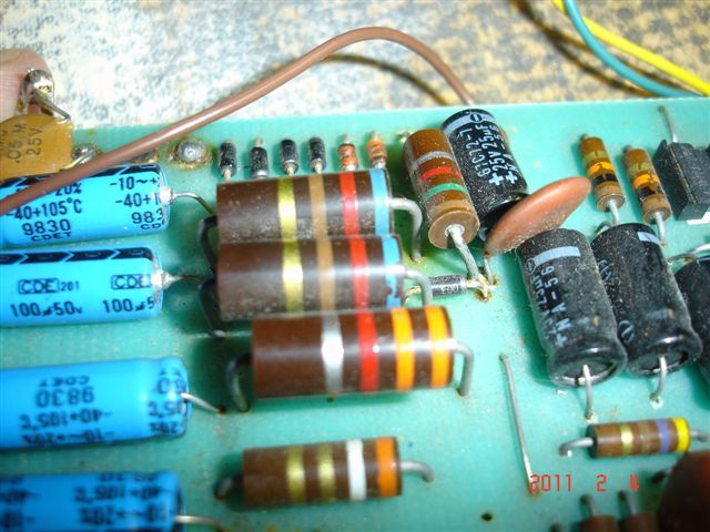
here's a picture http://www.volume4u.com/images/001.jpg http://www.volume4u.com/images/004.jpg | ||
| Lars Verholt (lmv) Username: lmv Registered: 11-2009 |
Terry, are you talking about the 1.5k/10W screen supply resistor? Duane: Check the four 470ohm resistors in the bias circtuit (R54-55-56-57) and also check the votage on the wiper of the bias pot (junction of R54 and R56). The voltage should be between 0.6V and 1.2V . Cheers, Lars Verholt | ||
| Terry Loose (terry) Username: terry Registered: 05-2006 |
After looking at the picture....it looks like the driver transistors they say 2N4292 and they should be 2N6488. I know that on some of the schramatics they give you 2N6292 , but use 2N6488. Also the two capacitors that are to the left of the bias pot look to be in backwards. Check to make sure you have them in right. What is the yellow capacitor in the lower right corner by the screw going to? It also appears that the power tube socket on the left you have a diode, but none on the right. If that is the case, take the one out on the left, you don't need them. They were only there in case you had a short that it would go to ground. But most are no good, so just take them out. Send me a bigger picture of the tube sockets and that area of the board. Send it to my e-mail address if you want or post it here. And yes, Lars, if you have the 1.5k resistor, then the amp uses 6CA7 tubes. Because some of these amps have 6L6 tubes. So that is the best way to check. | ||
| Duane Pfeiffer |
Lars, I've replaced the four 470ohm bias resistors already. The voltage on the wiper of the bias pot goes from .6 to 1.2 as I turn the pot ccw. Terry,I had 2N6488s in there and I changed them to 2N6292 just to see if things would work better. I don't think it makes much difference but I'll put the 2N6488s back in. The two 22uf caps to the left are installed with the negative end towards the op amp. My CP-1 schematic shows them that way. My CP-2 schematic shows them as non-polarized. ?? | ||
| Terry Loose (terry) Username: terry Registered: 05-2006 |
Turn the 22UF caps around. look at the pic I put up on bad repairs the caps are turned. | ||
| Duane Pfeiffer |
THE AMP IS FIXED! YAHOO! You guys are awesome! It was the two caps that were installed backwards. Thankyou, thankyou, thankyou! | ||
| Terry Loose (terry) Username: terry Registered: 05-2006 |
Duane, I'm glad that your amp is OK and it wasn't anything too serious. I know all the guys that helped with your situation are also relieved that the amp was fixed. Because that is why we are all on here...to help others. Next time maybe you'll be able to help someone in need out. Terry | ||
| Duane Pfeiffer |
Hey I wanted to give you guys an update. After I got the amp working, I played it soft at first, then when I played it with gain/volume way up, a fuse blew. I remembered that Terry mentioned diodes across the power tubes' pin 3 to ground. So I removed them and everything is working now. But I think the gain knob is doing something a little off. However, I don't really know what this amp is supposed to sound like so this might be normal. I'd like to get some opinions. Here's the symptoms. Most of the gain happens around 7.5 to 10 on the gain knob with a big jump at 9.5. Also, when the gain is set to around 8, I get intermittent distortion rather than a light distortion. In other words, I strum my guitar and get what I would expect (light distortion). Then after a brief pause I get an ugly distortion that sounds like the speaker is blown. I can do a recording this weekend if that helps. Thanks. | ||
| Duane Pfeiffer |
I still am not happy with the sound I'm getting from this amp. There is a weird 'farting' sound when the gain is at 8. It also seems that there isn't enough volume until the gain is at 9, then the amp 'turns on' and the volume jumps quite a bit. Since the schematic is wrong as far as the orientation of C24 and C25, I'm wondering if other errors exist. What about C16 and C18 on the gain and volume pots? Is the schematic for GP-1 correct? Here is what I'm observing at this time. I bias the amp with the lowest side at 25mV and the higher side is at 31mV or so. When I apply a signal and crank it up, the low side hovers around 100mV and drops as soon as I stop playing. However, the high side climbs to over 300mV and does not seem to drop when I stop playing. I've also observed that the high side tube is beginning to red plate. I've measured resistance on both sides across the 3.9 bias resistors and they are at 4.5 ohms. The 470 ohm resistors measure the same on both sides. | ||
| Lars Verholt (lmv) Username: lmv Registered: 11-2009 |
It's obvious that one tube/driver transistor pair is not entirely stable. You mentioned earlier in the thread that your grid bias voltage was only 16V. Is this still the case? It should be 22V which would bring your tube to a different spot on its transfer curve. If a resistor measures 4.5ohms, is that with or without the meter's offset reading? About 0.5ohms for offset is not unheard of, so that would bring your cathode resistors at the right value. Cheers, Lars Verholt | ||
| Duane Pfeiffer |
Lars, grid bias voltage is at 23V on each tube. I don't know what this means but I hooked up my oscilloscope and injected a sine wave to the high input (bypassing preamp). The waveform is reproduced nicely through the circuit until I crank the volume/gain both above 8. Then I see a blur on the rising edge of the wave form. Does this tell us anything? | ||
| Bill Traylor (bozzy369) Username: bozzy369 Registered: 02-2008 |
what is this crap above me?^ | ||
| Mike Kaus (mm210) Username: mm210 Registered: 05-2006 |
ug-look like spam. Don't know how they got in since we register now. Hacked? | ||
| T.E. Price (uposb4) Username: uposb4 Registered: 05-2006 |
Must be hacked because the user name would have to be changed and would show the jumble name shown here in the user account page. Just another loser with no life. | ||
| T.E. Price (uposb4) Username: uposb4 Registered: 05-2006 |
...or it could be Lassie trying to tell us Jimmy fell in the well again. | ||
| Mike Kaus (mm210) Username: mm210 Registered: 05-2006 |
Don't know how these guys get in but they're gone for now. MIke. | ||
| Bill Traylor (bozzy369) Username: bozzy369 Registered: 02-2008 |
poor Duane,since you got rid of the spam posts it looks like we are all giving him hell,lol | ||
| Mike Kaus (mm210) Username: mm210 Registered: 05-2006 |
Yeah, that is an unfortunate side effect of assholes crashing the party. NO OFFENSE DUANE! | ||
| Lars Verholt (lmv) Username: lmv Registered: 11-2009 |
Well if nothing else it made me look at this thread again as I apparently missed Duane's last post. Duane: If you inject signal at the 'hi' insert point, you would be bypassing both the gain and volume controls. So, I am not sure I comprende totalemente  Anyway - it is a good idea to inject the signal after the preamp part. The signal goes through one driver stage after which the signal is inverted by another amplifier stage in the same chip *but just for one of the two output tubes*. If you are getting a peculiar waveform when you turn up the signal but only on one half wave, it may come from the inverting stage. Clear as mud? -Lars Verholt | ||
| Mike Kaus (mm210) Username: mm210 Registered: 05-2006 |
Ok-after deleting over 100 spams in spurts today, let's see if this keeps them out. Mike. |
Tue, 03/25/2014 - 09:34
#1