| Author | Message | ||
| aryl |
i opened up my 112rd 100 today to check bias. first thing i noticed was that the bias cap on the right leg from power tube pin 6(the amp upsidedown and the faceplate pointing away from you) had a burn mark in it. i went on to check bias and found that setting the left 3.9 ohm resistor to 23mV, the right 3.9 ohm resistor is about 5mV above that. i left it on and checked it periodically for about 45 minutes. the voltage rises. slowly, but it definatly rises. is this normal? could the shady cap have something to do with this? i also noticed that the cap on the left leg says 3300/10 630V and the one one the right says, from what i can make out, 2200/5 530V. should these be different? i couldn't seem to find them on the schematic. they are both yellow mallory's. | ||
| Anonymous |
Had a 210-65 that had upward bias 'creep'. Re-capped all electrolytics, still had the 'creep'. Replaced the 2 bias transistors and the bias stabilized. Re. the 'burnt cap', if you see something that needs maintainance, do it before it becomes an issue. | ||
| aryl |
i was fully planning on replacing the cap. the value was what i was wondering about... | ||
| aryl |
how exactly do you read mallory caps? | ||
| Steve Kennedy (admin) |
If you cannot discern the value of a capacitor, find its location on the schematic and read the value there. Larger (electrolytic) caps will read like: 25?F, 50Vdc Smaller caps (disc caps) will read as: 0.1?F, 600Vdc The first term is the capacitor value in microFarads. The second term is the "working voltage" (or maximum voltage rating) in Volts DC or AC. Steve | ||
| aryl |
steve, the yellows are set-up with three numbers. for instance, one of mine says 1/10/100. and another says 3300/10 630v. the second example cannot be in microfarads, as it is way too small. it has to be nano or pico. thank you. david | ||
| Steve Kennedy (admin) |
In this case, my first guess would be 3300pF, 630Vdc and 1uF, 100Vdc. I'm not sure, but I believe the "/10" may mean "10%" tolerance. Steve | ||
| aryl |
heres a picture of the caps that are in my amp but not on the schematic. one on the left is 3300/10 630v and one on the right is 2200/5 530v( soldering tip burn) 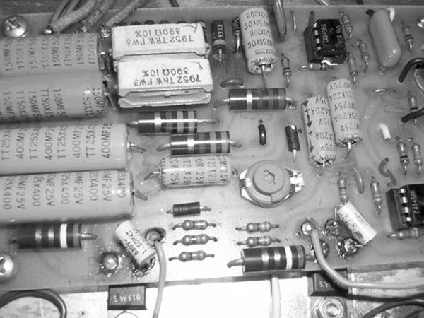 | ||
| aryl |
heres a link to the schematic: http://www.ernieball.com/mmonline/techin fo/old_amps/2165-rd_&_2100-rd.pdf | ||
| aryl |
steve, i think you're right about the middle numbers being tolerance. | ||
| aryl |
i'm not sure if i should take the caps out or not. any thoughts? looks to me that the caps have something directly to do with pin 7 off the output tubes. sorry if i'm too persistant. i'm trying to learn, as well mess as little stuff up as possible at the same time. | ||
| Steve Kennedy (admin) |
Look at the driver transistors... they have a Motorola "M" on them, meaning that these are not the original driver transistors, but replacements. These caps are across transistor connections it appears and may be used as compensation capacitors which are keep these transistors more stable. The replacements may have a much higher frequency response than the originals, which can cause them to enter self-oscillation more easily. These caps may be necessary in you amp circuit with these transistors. They wouldn't be on the original schematic as the original JE1692 transistors didn't need them. The values are small and I doubt they would effect anything in the audio spectrum, especially the restricted bandwidth of a guitar amp. Steve | ||
| aryl |
booyah!! |
Tue, 03/25/2014 - 09:26
#1