Hi all,
I'm working on a friends 112 RP 65. It's a GP-3A version, with the 6L6GC tubes.
The reported faults are: "as some buzzing whenever it's on, the volume stops increasing after you've turned to maybe 4 or 5 and the reverb doesn't work at all."
I suspected filter caps before opening it up and, sure enough, the 2 x 100uF/450V caps in the dog house are bulging.
I'll also replace the other filter caps too - 2 x 150uF/50V and 2 x 400uF/25V. I may or may not replace the other 7 x 20uF electrolytics (might as well while the board is off).
The question I have is - what's going on with those rubber bits on the +ve end of the 400uF caps?
Images:
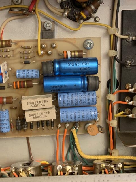
Insulating sleeves?
They could be insulating sleeves to support and protect the leads. If you're replacing caps, check and replace any tired or blown zener diode regulators. There are 2 at the bottom of your picture for +/16V. D19,20 IN5353. There's another, D18 IN4748 +22V for tube grid bias. If you replace any zeners, stand the new ones off the PCB 1 or 2 mm for better heat dissipation. -mgriffin
Thanks! I'll order those
Thanks! I'll order those zeners when I order the caps.
Am also contemplating replacing the op-amps as this amp seems to have odd values. The circuit says ICs 1 & 2 (input + gain stage) and 5 & 6 (reverb send/return + buffer) are LF-353, and all others ICs are LM1458. This amp seems to have an LF353N and a TL072CP in the phaser circuit, and a mix of 1458s elsewhere (MC1458CP, MC1458P, CA1458G).
Cheers,
R.
They're all Good
All three of those op-amps are interchangeable. Here's a video that tries to demonstrate tonal differences. https://www.youtube.com/watch?v=DlKAXTMKpjI
Also, visit the Downloads and Resource page on the Top Bar for your RP schematic. It tells what each IC type should be. The TL072 was not on the list BTW, but will work. http://www.pacair.com/mmamps3/sites/default/files/docs/2165-rp_and_2100-...
Good luck -mgriffin
Thanks - I've got the GP-3A
Thanks - I've got the GP-3A schematic. It says:
IC's 1,2,5, & 6 are LF353. All Others are LM1458.
I'll buy a few spares and fit the correct type as per the schematic.
R.
I've just realised, I'm going
I've just realised, I'm going to have to unbolt the driver transistors from the chassis to get the board out to replace the caps. Do I need to do anything special when I re-fit them? Presumably, some thermal paste between chassis and transistor?
Insulators
Yes! Use thermal paste and reuse the insulator parts that are there. Good luck.
Perfect! Thanks. R.
Perfect! Thanks. R.
Mystery of rubber bits solved!
Well, that mystery is solved. Those rubber bits are the internals of the capacitor!
Status update
A quick status update...
I've replaced the main filter caps and (nearly) all the electrolytics (I missed C28, a 2uF cap in the phaser circuit as it was a silver Sprague, not blue like all the others.
The amp is sounding much better now - hardly surprising, given the state of the original caps!
There's only one issue left to bottom out. Here's what the owner said:
Now, I can see what he means. When the gain is turned down, the volume does indeed seem relatively ineffective. However, if the gain is turned up further, the volume control also seems to do more.
Is this a characteristic of this model, ie. is it not an amp with a lot of clean volume, ie. gain turned down, volume up? Or is there something wrong that I need to address?
Thanks,
R.
Post-caps replacement
Gut shot after I've replaced the caps:
Gain Pot?
Has the Gain pot ever been replaced? If yes, is it the correct taper? They're unusual Dual 100K Reverse Audio Taper. -mgriffin
Good question. I shall ask
Good question. I shall ask him.
I don't believe he's had it long so he probably won't know. Is the volume pot linear?
R.
Volume Pot
According to the schematic, the volume pot is linear taper. Measure the Gain pot with a DMM. It may have a break at one end. Check it's resistance behavior as the shaft is rotated from 0 to 10. If you haven't already, it may be worthwhile to give the electronics a good cleaning. Pull all IC's one at a time and re-seat them using contact cleaner on the sockets. Clean the tube sockets & pots too. A clean amp is a happy amp. -mgriffin