Hi all.
I got sick of the whooshy windy noises my amp was making, so I decided to get a new pair of output tubes.
It currently has Sovtek 6L6WXT+'s in it, and I've got a pair off JJ Tesla 6L6GC's to go in. Before I put them in, I figured I'd take readings with the current tubes, so I could see what happened once I put the new ones in. Anyway, I measured 4mV and 14mV across the 3.9 ohm resistors (which incidentally measure 4.5 ohms and 5 ohms each). That seems really low based on the 25mV I've read they should meter at, but besides the whooshing noise, it sounds pretty good. Whats the go here? I'm a bit scared to change the bias so drastically when it seems to sound good... What would be the audible symptoms of such a cold bias?
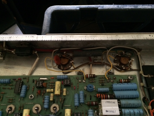
Another odd thing is there are two capacitors soldered across pins on one of the tube sockets (see pics) that aren't there on the other socket. Seems odd.
I also noticed that the two big Mallory 100MFD 450V filter caps in the can under the chassis are starting to show signs of mushrooming, so I've ordered replacements for those. In the end, they are probably what's causing the windy sounds, but I've owned the amp 8 years and never replaced the tubes, and who knows how old they were then...
Any thoughts on the low bias setting? I have a rehearsal on Monday I need the amp for, and ideally I'd like to play the new tubes if possible. I've left the amp as it was for now...
Cheers,
Reuben


Just for interests sake I
Just for interests sake I pulled the tubes out and measured 760 volts on pin 3 on Hi and 500V on Lo, 380V Hi and 225V Lo on pin 4 and about 22V on pin 5 on both Hi and Lo (could've been -22V, but there were reflections on the multimeter screen). Measurements were identical on both tube sockets. Does that sound about right?
Cheers,
Reuben
RD 65 112
Let me give you the bad news. You say you put new 6L6 tubes in the amp. Now the bad news....This chassis is set up for EL34/6CA7 tubes. When you look at the tube socket on the left side of the picture, you see the big black resistor off the tube socket, that means that this amp was set up for EL34's. So this is an early production run, because later on they did use 6L6 tubes. Also you can see from the picture you have all the blue Mallory caps. These are all original and 35 yrs. old. and need to be replaced with some new Sprague/Vishay TVA caps. You can get them from Mouser. The caps underneath the amp are the 450 volt/100, you cannot use TVA caps. They are too big. You have to use Illinois Central or something else. Also the cement resistors, look like they have been changed...they look pretty white....check them out. This should get rid of your hissing. Good Luck.
Terry
Thanks Terry.
Thanks Terry.
It has been running happily for the last 8 years and sounding good with 6L6's in it. Not saying you're wrong, but is there going to be an issue if I continue to use them? I haven't put new tubes in yet, as I decided to take some bias measurements first which is when I got concerned, given how cool they seem to be biased. Is there any way to tell for certain which circuit I have? I can't see any identifying numbers on the top or bottom side of the board. From looking at the caps on the tube sockets (470pf 3kV which I think are C35 and C36 on the schematic) I think I have a GD2...
What mods would I need to do to convert it to 6L6 spec?
I've ordered F&T 100uf 450v caps. I'll get to the smaller blue Mallorys soon... It's a 'one step at a time as cash flow allows' kind of project...
Cheers,
Reuben
I've been through the
I've been through the schematics from input through to the power tubes, and besides a few variations in component value (mostly resistors), the circuit is virtually the same.
When I get to the power tubes, I can see that's where the circuit varies slightly and there are a couple of parts of the schematic which I don't quite understand. On the GD2 circuit pin 2 and pin 7 of 6CA7 are connected to 6.3V AC (heater filaments). On GD2A Pin 2 and 7 are also connected to the 6.3v AC supply, but there is a link from pin 2 to ground. R39 and R40 which are connected to the emitters of Q1 and Q2 are drawn to the same ground point. Does that mean anything, or was it just a convenient way to draw the schematic? What's the go here? On GD2 the emitters look to be connected to ground but there is a 50pf cap to pin 4 that is drawn to the same ground point. Again, does that mean anything, or was it just a convenient way to draw the schematic? What is the function of that cap, as it is not present on GD2A? On GD2A there is a 470 ohm 1W resistor connected between the filter caps and each pin 4, on GD2 there is a single 1.5k ohm 10W resistor. These are the only real differences I can see. The only other thing I'm curious about, is there is a orange disc cap that's labelled .1M 100V that goes from pin 6 to pin 1 on one tube socket, but not the other. I'm trying to figure out what it's for, and if it is in both circuits, or if it is an addition... Am I right in thinking that pin 1 is connected to ground, and pin 6 is an unused pin, so it could just be a convenient place to attach it?
If I'm reading this all correctly, I remove the 50pf cap and remove the single 1.5k ohm 10W resistor and replace with 2 x 470 ohm resistors (1 watt drawn, but I'm thinking 2w or 5w would make more sense here?) to each pin 4. What about the pin 2 to ground? Am I close, or have I totally cocked something up?
After speaking with my amp
After speaking with my amp tech I've bitten the bullet and put the new tubes in. I've warmed up the bias so it reads 39mV and 20mV. The tubes are a matched pair, so I'm guessing this imbalance stems from something else. Any ideas?
There is a definite improvement in tone from the old tubes (less noise too), but it still breaks up a little earlier than I think it should. I'm not sure if it is the humbuckers in my guitar pushing the preamp too hard, the tubes being biased too cold, or another problem (old caps etc)... It's always broken up fairly early, and it certainly isn't any worse now than it used to be. To be honest, I kind of like the sound, but I want to make sure that the amp is in proper working order so I can get another 8 years out of it trouble free... Any thoughts?
Cheers,
Reuben
So I borrowed a mates Strat.
So I borrowed a mates Strat. Turns out the dirt is from my guitar.
Anyway, bias has settled at 44mV and 20mV for now. I'll do the big caps in the can this week, and then replace the rest of the electrolytic caps,the driver transistors and the 1.5k grid resistor with a pair of 470 ohm 5 Watters as per the GD2A circuit and see how it goes from there.
For now, it's sounding good and will get through rehearsal tomorrow...
I wouldn't operate your amp with this problem.
The quiescent plate current (Bias current at rest with no signal) should be no more than 21 or 22mA on the Music Man amps. This is because the plate voltage is almost double that of a "generic" tube amp output stage (so the bias current must be about 1/2 that typically seen in other amps). The bias current should be balanced within a few mA between the tubes (2-5mA). Start with a properly matched set of proper output tubes and go from there.
As Terry indicated, the presence of the 50pf cap and single 1.5K resistor connecting to the Pin 4s of the output tubes only applies to those older amps designed to work with 6CA7 or EL34 tube types. This is clearly seen by comparing the schematics in this area.
You are indicating a HUGE difference (greater than 2:1) in bias current between the output tubes and this indicates some other problem (mismatched output tubes, resistor changed value or a bad transistor driver most likely). You need to find out why the bias is so different and fix that problem first before taking the amp out and playing it with this gross bias mismatch because this could cause even more damage to your amp or output tubes!
Shotgunning parts without troubleshooting to find the real problem can be a recipe for disaster! If you have an amp tech is there a reason why isn't he looking at the amp? If he doesn't want to deal with transistor circuitry or this type of design I would respectfully submit that you might need a different amp tech for this amp. There are Factory Service Bulletins (compliments of Terry Loose) posted on this site that have several documents possibly relating to your amp, in addition to the schematics.
In the dark you may see the 44mA tube plates glowing a dull red already in HI power mode! Restricting the amp to LO power mode might help relieve some stress but the amp is just not healthy right now (regardless of how it might sound to your ears).
Remember, tube amps sound their best just before they blow up!
Thanks for the response.
Thanks for the response.
Firstly, my amp tech is about 500kms away over a large body of water in another state, and I like to do things myself (I do most of the work on all my cars when possible etc). We have already rebuilt an early '63 blackface Fender Bandmaster via email and it is still going strong 4 years later (me doing the work with help and advice from my tech via email).
I have already ordered replacement driver transistors, plus the correct 470 ohm resistors for the 6L6's as well as the 2 new filter caps for the under chassis can. The rest of the electrolytics in the circuit will be replaced as soon as I can get an order together from Mouser or somewhere similar for Sprague Atom caps in the right values. They're hard to find in Australia it seems.
From studying both GD2 and GD2A schematics, the differences in circuit are really quite minimal, and some things have already been modified towards the 6L6 circuit by a previous owner or tech. 6L6's is what was in it 8 years ago when I bought it, and I've been using those same Sovtek tubes ever since, until now. Are there major differences in the circuit that I'm not seeing? My tech suggested it should be perfectly safe to use the 6L6's in it as it is, and if I wanted to I could remove the 50pf cap, and replace the 1.5k resistor, with 2 x 470 ohm resistors as per the GD2A circuit, and after that, there is not much difference. The other thing I noticed was that most of the 10uf 25v caps on the board in the EL34 circuit are replaced with 1uf 25v caps in the 6L6 circuit. Does this make a big difference, as I will be ordering replacements for those anyway, and could easily change the values.
Note that the Music Man factory process for biasing says to adjust the lowest tube to 25mV and the highest must not be higher than 55mV (note mV not mA) measured across the 3.9 ohm resistor from driver emitter to ground. I'm running at 20mV and 44mV, so according to the factory bulletin I could safely go higher. Is there a reason you disagree with the factory recommendation? The tubes were a matched pair, so my guess is also driver transistors, or one of the electrolytic caps in that section of the board. These will be replaced as soon as they arrive.
For what it's worth, I've only discovered any of these issues because over the last 2 years or so the old tubes were getting a bit noisy. They were biased a little cooler than I'm running these new ones (they measured 5mV and 16mV), and were even more mismatched in bias reading. If I hadn't decided to replace the tubes, I'd be happily using it as it was without a care in the world. True, that's not to say it wouldn't have eventually blown up, but the hiss and crackle that was present with the old tubes is gone, and there is no sign of red glow on the plates.
Balancing the Output Tubes
Hello Fiat CC,
I have an RD65-112 and did the same thing as you're doing with respect to the to the driver transistors, emitter resistors and bias network resistors. Previously I had put in a matched 6L6 GC pair of tubes to replace the original Sylvania's. Just replacing the tubes did not improve balance significantly. I believe I measured about 25mV and 45 mV on the 3.9 Ohm resistors after tube replacement and warm-up. BTW: the 3.9 Ohm resistors measured at about 4.5 and 5 ohms, well beyond 5%. After replacing the transistors, 3.9ohm emitter resistors and the 470 ohm bias network resistors with well matched and correct values (<1%), the tube bias voltages matched extremely close...like 25 and 25.5 mV respectively. I reckon I got lucky when I ordered the parts from Mouser. All parts were on the tape from a dispenser reel which told me they probably came from the same batch when manufactured. That is so much better than loose parts grabbed from a bin. They certainly were well matched. Good Luck. You seem like a pretty sharp dude.
mgriffin155 - Mike
Ooops... Difference in expected terms.
Sorry about that! When you said "Bias stabilized at 44mV and 20mV" my brain filled it in as "mA". I have learned never to use the Factory biasing method as written but to use it as a guide to do it properly. Measuring voltage across the resistor is not actually measuring quiescent bias current but is only an indicator that relies on the resistors being acccurate, the transistors being matched and the tubes operating properly so it can be misleading because you are looking at a remote "symptom" and not an actual measurement of the tube's plate current. Tube circuits can have other problems that add or subtract plate current through alternate paths that cannot be seen by measuring at what are essentially transistor-isolated cathode resistors. I always measure bias current directly so I can spot problems that are invisible to the "factory" method.
Simply converting "mV across a resistor" into mA with Ohm's Law yields a factory setting range of 6.4mA to 14.1mA. This range was probably "acceptable" to Music Man for several reasons.... while it is colder than what is sonically desirable, it helps the tubes outlast their warranty period and the range is pretty big because the factory didn't bother to use pre-matched tubes. With factory settings like these it is no wonder that 40 year old amps can still have their original factory tubes but they can sound better than that if matched and optimized. With matched output tubes you get much closer matching on the bias current (assuming a properly balanced & working amp) which allows a higher (18 to 22mA typical) bias setting with both tubes being more nearly identical. This is more important now than when the amps were made because the tubes available today are simply not as good as the U.S. made originals.
Not having a local tech does tend to make you try to do it yourself! It makes it difficult to fix many types of problems because actual troubleshooting will fix more problems quicker and cheaper than guessing what might be wrong and trying to replace parts in the hope that you can fix an issue. It can be compared to ordering lots of parts to fix an automobile symptom (which can be caused by numerous possible failures). It would theoretically be possible to spend more than the car (or amp) cost when new and still not fix the problem or cause even more issues because you swapped out good working parts for potentially inferior new ones!
If you are going to modify the amp for using the 6L6 output tubes check out the Factory Service Bulletin regarding a modification that was made to 6L6 amps because of an instability that arose when the factory Sylvania 6L6 tubes were changed and I found this to be true with other brands as well! I saw this first hand on an HD-150 amp (with an unstable intermittent oscillation problem only visible on an oscilloscope ) and the mod fixed it right up. This was never necessary on the 6CA7/EL34 models.
I am considering buying a
I am considering buying a bias meter from Weber or somewhere similar. I do realise there are limitations with the factory method, but it seemed to me that it would at least put me into a safe zone, and if it sounds decent then that's good for the time being.
I do understand your thoughts regarding finding a local tech, but it was my experience with a local tech that started me down the DIY amp route in the first place. My dad has owned a 63 Fender Bandmaster for a long time. Sometime in the early to mid 90's it burned a tube. A helpful (but knowledgeable) mate put in a spare pair of 6CA7's he had lying around, which caused all sorts of issues in that amp, and then it was shelved for about 12 or 13 years. When he decided to resurrect it, he sent it to a tech who replaced the 6CA7's with more 6CA7's (even though the tube chart in the amp is still intact and clearly states 6L6GC), blew those tubes, and charged us for the trouble. After that I decided I'd find someone who knew what they were doing and could help me do the work remotely. We got the Bandmaster going with a lot of back and forth email, and now it sounds great.
I am aware that, since I don't have a scope etc I am limited in my trouble shooting ability and that I can end up replacing parts that are still working, but then $130 for all the parts to do a re-cap, replace the transistors (my tech has matched me a pair of 2N6488G transistors) etc seems pretty decent when you compare that to what it would cost me to get a tech to do any work on the amp. Since the amp is now 30+ years old I figure it's due a re-cap anyway. I can run a multimeter over all the resistors on the board to see if any are way out of spec, then after that it's really down to IC's, and since the amp functions and sounds good, I'm prepared to believe that the IC's are in good working order. Incidentally the 3.9 ohm resistors measure 4.5 ohms and 4.9 ohms, so are a bit our of spec, and I'll probably replace those when I do the transistors. Mind you, they were possibly nearly that far out when they were made (with a 20% tolerance etc). I also wondered, since they didn't bother matching tubes, whether the transistors could've been wildly mismatched from new also?
Thanks for the heads up on the 6L6 service mod. I do remember seeing that, but didn't think about it a great deal at the time. I'll look into that one.
Cheers,
Reuben
Bias
Since YOUR amp is an RD, the BIAS is actually driven by the transistors. They are NORMALLY measure by the bias meters by interrupting the stream between the tube and the socket on pin 8 and either measuring it as a voltage, with a resistor or TOTALLY interrupting it and measuring it directly as a CURRENT measurement. That's with a normal(SIC) anode or plate driven amp. The cathode is going to ground in those cases. In your case, your amp is DRIVEN through the cathode so you might as well measure it with the resistors. To be honest with you, I've never even TRIED to measure a cathode driven amp with an interrupter type device so it MIGHT work but why? Maybe Lars has tried it. He's more familiar with RD's.
Bias & Resistor measurements
Measuring most components "in circuit" is problematic at best. A circuit is a collection of parts all interconnected in various different configurations. An out-of-spec part or failed component may or may not measure much different than when everything is as it should be. In order to be sure you making a proper evaluation of a single part you have to lift one or more legs out of circuit to isolate the component enough to make a valid measurement. Otherwise, you can be deceived and come to the wrong conclusion.
Measuring the plate current of a tube directly is the only way to catch every potential source of current. An output tube has many more connections than just a cathode and plate. If any of these elements get grounded or shorted or connected to a leaky or failed component then additional current sources or current sinks will be created and many of these will not be visible by simply looking at the source resistor at the cathode. You can have that Cathode resistor out of spec (or bad) and adjust the bias to be erroneous because the measurement is based on that in-circuit resistor.
You can measure that "proper" voltage across that 40 year old cathode resistor and not even see ANY plate current under a variety of possible conditions! Conversely, it is also possible to see no voltage across the cathode resistor and still see an output tube "red-plating" as plate current leaks in from another tube element or failed component. You simply cannot trust that resistor measurement bias method under all conditions so it makes sense to use a bias probe so you see the "bigger picture" and get the bias current adjusted correctly or determine if there is another problem.
Using a bias probe puts the precision of the measurement squarely on an outside 1% resistor that is a part of the test gear that is not subjected to constant use and accumulated thermal deterioration placed on the in-circuit "cathode" resistor & transistor. It also places the point of measurement where it can "see" the big picture (at the plate) where the B+ source is applied.
I have chased my own tail a time or two (more times than I can count, actually) relying on in-circuit readings that are determined solely by in-circuit components. Not everything is as it seems unless you can isolate and introduce a known trusted element that does not live in the circuit being tested to act as a "reality check". That is what a good piece of test gear properly employed (like a bias probe) can do for you.
This is just my opinion based on observation and experiences. Since troubleshooting bias and output tube issues centers on the circuitry that works the hardest and hottest in an amp, I have found it best not to rely on assuming that everything matches the schematic. It is one way to go that I have found that cuts through a lot of potential problems and avoids wasting a lot of time based on erroneous information.
Well, the big caps for the
Well, the big caps for the can have arrived and the drive transistors and 470 ohm resistors are in the mail. Next on the list is the rest of the electrolytics. Yes, I could perhaps save a bit of time and money if I had better testing equipment. On the other hand, I say why not try and return it to as close to 'as new' as possible.
I may try and find some precision 1 ohm resistors so I can take measurements without need to splash out on expensive bias probes, since my multimeter is perfectly decent...
No Problem... it's just my opinion!
I wasn't trying to tell you what to do, just point out some of the pitfalls of approaching an issue with a shotgun! LOL!
"Restoring to new" by changing a lot of parts isn't quite what you might think it is. If your goal is just proper operation of the amp you can do it but "restoring" and amp to original condition and reliability is much tougher. Many components just are not made as well as the factory originals (tubes and filter caps come to mind). Really fine filter caps (or NOS Tubes) are extremely expensive now days (much more expensive than a bias probe) and most of those commonly available at reasonable prices are just not made to the same specs or quality level as the originals. Also, carbon comp resistors are getting increasingly more difficult to find and carbon-film or metal film resistors are not the right components to use in many tube amp circuits. These new parts may not only not work as well in some circuits but may also become additional sources of failure!
The 1% 1-ohm resistors would have to be inserted in series with the plate of the tube in order to make the measurement and this can be dangerous and very time consuming if you simply unsolder the the plate wire and solder the 1-ohm resistors in. You won't want to leave them in there (or you would have to have beefier ones because the entire current of the tube is flowing through these when the amp is operating and being in there all the time negates the reason for having them a part of a bias probe so they don't deteriorate while they are not in use) and you will have to ensure that the high-voltage B+ is drained before inserting and removing the resistors.
This is why a bias probe adaptor for your meter is a much smarter way to go. It costs only about as much as a single output tube, doesn't requiring re-wiring or modifying your amp to use and is a huge enhancement in safety (think Life Insurance Policy) when working with 700Vdc! You don't need an expensive one with its own meter display. It is a very sound investment if you are going to work on your own amps. IMHO
It's all good. I sounded more
It's all good. I sounded more defensive than I intended, lol.
You've sold me on a bias probe. Hadn't though of the component deterioration...
I am using Sprague Atom caps as recommended by my tech. He suggests these or F&T (or some TAD parts). These seem to be pretty good. They're what I put in the Fender Bandmaster and it sounds nice.
Filter caps
Yes, Sprague, F&T and TAD are good choices. Unfortunately, there used to be many more choices at much lower prices than today. Electrolytic capacitors are the one component you can't normally stockpile for decades because similarly to batteries, they can chemically deteriorate, dry out or leak over time while sitting on the shelf.
Don't pass up Illinois caps
Don't pass up Illinois caps just 'cause they are cheaper. I've put a LOT of them in and had no failures. They are used in a lot of OEM installations too. Along with Panasonic. Just sayin.....