| Author | Message | ||
| Bill Moore (bill_moore) Username: bill_moore Registered: 03-2013 |
I have been dutifully reading the posts here to find out more about my (new to me) amp. I am a hobbiest, and enjoy tinkering with music equipment, but was unfamilliar with MM designs. I finally opened it up last night to verify the need to change components in the HV power supply section, but was surprised to find the low voltage section was the problem. Enough heat had been generated with the 390 ohm 3W resistors, that one was loose in the circuit board, as was one of the 5W diodes. I still plan to change caps, and diodes on the HV side, but will also have to rebuild the low voltage filter section as well. Another interesting design feature was the TO-220 transistors heat sinked to the aluminum chassis. I've seen that on newer SS amps, but when this amp was built, most others were installing dedicated heat sinks. | ||
| Bill Moore (bill_moore) Username: bill_moore Registered: 03-2013 |
I finally got the power/filter supplies rebuilt, and last night I fired it up with a bulb limiter in line. Standby, (also no tubes installed), no limiter bulb illumination, checked voltages at various points, low, but consistant. When switched ,(lo, or Hi), bright bulb illumination, and hum from speaker. Disconnected center tapped wire to OT, and checked voltage to stand off. 450+ in LO, and 685+ in Hi. Bulb limiter barely glows. I guess my next step is to lift the Blue and Brown wires from the tube sockets, and see if I still have a draw. With the center tapped wire disconnected, no primary OT wires are shorted to gnd., approx. 3.8K ohms from CT wire to either brown, or blue. Am I overlooking something? I sure hope the HV diodes, or caps are shorted rather than the OT. I had planned to replace those diodes, but couldn't find any, and found they are protection for the OT. Any advice will be appreciated! | ||
| Mike Kaus (mm210) Username: mm210 Registered: 05-2006 |
Really sounds like one of the filter caps is backwards to me. Did it work before the re-build? SOME of those caps can be confusing as to which end it + and which is -. Also, some HAVE been mis-marked. Used to be, the exposed end with the aluminum cap showing was ALWAYS the - end but I ordered some the other day that have both ends covered in the insulator. Just asking. Mike. | ||
| Bill Moore (bill_moore) Username: bill_moore Registered: 03-2013 |
Thanks for posting Mike! I got back to it saturday, and lifted the MR250-5 diodes from the transformer connection at the tubes, and lost the draw. I tested the diodes, and 1 is shorted, so I reattached the other. Guess I'll start again searching for a replacement. I reassembled the amp until I can find another diode. I don't think that the volume level I'll be using it, that it needs the extra protection anyway. The amp sounds great! I do think the drive channel is a little harsh, thinking to maybe swap some different op-amps, and see if it makes any difference. | ||
| Mike Kaus (mm210) Username: mm210 Registered: 05-2006 |
Seems to me Lars found a substitute number for the diodes. I think he said they were 5K volts! You might search for his post. | ||
| Bill Moore (bill_moore) Username: bill_moore Registered: 03-2013 |
I found that post, Mike, but the 1N1734A is as elusive as the original part, but I'm still looking. Another tech said I could stack 1N4007 avalanche diodes to get the proper voltage. | ||
| Bill Moore (bill_moore) Username: bill_moore Registered: 03-2013 |
Found Peavey #70402873 diodes are availlable. 2KV, 250ma. Figure I'll stack (series),2 per leg, and should be close to the obsolete diodes. | ||
| Rob Flindall (flinly) Username: flinly Registered: 12-2012 |
Bill, After reading your post, I took a look at the board in my 112RD-100. The circuit is GD-2A (May 1981) The 390 ohm resistors and adjacent diode have a dark discolouration on the board. Is this what you saw on your 115RD-100? 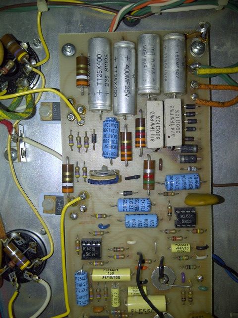  | ||
| Lars Verholt (lmv) Username: lmv Registered: 11-2009 |
Supposedly this company has a few of the 1N substitution: R/C Metals Electronic, Inc. Dba: Freelance Electronics 13197 Sandoval Street Santa Fe Springs, CA. 90670 P (562) 204-0611 (800) 300-1968 F (562) 204-0621 I was about to place an order when I discovered that their credit card form does not use https, so I'd feel more secure calling first and then maybe faxing credit card info. Anyway, just thought I'd pass it along. -Lars | ||
| Bill Moore (bill_moore) Username: bill_moore Registered: 03-2013 |
It looked exactly like that, Lars, one of the resistors, and one of the zeners were unsoldered from the board. While I was there, I replaced the caps, and 1N4003 diodes, as well as the 390 ohm resistors, and the 16V zeners. Thanks also for the source tip, I have decided to replace the diodes with R3000 like used in Fender. They are rated 3KV, 250ma. I don't think I will need to worry about it at the volume levels I'll be using the amp. | ||
| Bill Moore (bill_moore) Username: bill_moore Registered: 03-2013 |
It looked exactly like that, Rob, one of the resistors, and one of the zeners were unsoldered from the board. While I was there, I replaced the caps, and 1N4003 diodes, as well as the 390 ohm resistors, and the 16V zeners. Thanks also for the source tip, Lars,I have decided to replace the diodes with R3000 like used in Fender. They are rated 3KV, 250ma. I don't think I will need to worry about it at the volume levels I'll be using the amp. | ||
| Bill Moore (bill_moore) Username: bill_moore Registered: 03-2013 |
Sorry about the posts, guess I don't know how to edit! | ||
| Rob Flindall (flinly) Username: flinly Registered: 12-2012 |
Thanks Bill, What does this section of the circuit do? What are the symptoms of this overheated section? Is it necessary to repair? | ||
| Bill Moore (bill_moore) Username: bill_moore Registered: 03-2013 |
Rob, most of the components there are the LV power supply/filters. Look at the schematic, and you will see the section as it connects. At the burned point itself, is the 16V zeners, and the (voltage dropping?) resistors. I didn't check the components I replaced in mine, I just considered it maintainence. | ||
| Rob Flindall (flinly) Username: flinly Registered: 12-2012 |
Thanks again Bill. This is some more information I got from my Amp Technician. In the photo that you have supplied in the attachment on the low voltage supply components, there is some heat stress around the 5 watt resistors, 390 ohm, and the 5 watt zeners ( 1N5353 ). This is a common problem in any guitar amplifier +/- 16V low voltage design due to the make up of the circuit. These supplies all the OpAmp?s in the amplifier and switching transistors plus any other circuit criteria that uses this supply in the amplifier circuitry. This is caused by steady currents and fluctuating currents during amp operation. Over time this will cause the components that you mention to heat over it?s maximum design levels, this is normal. You can?t get around this unless you redesign the power supply include the low voltage tap from the transformer or change the doublers design if there is one. We see this all the time and what we do here is to remove the whole board and redo the traces and solder mask on the P.C.B. other wise you will eventually have a decline in the voltage of the supply and will cause circuit problems. The Resistors and the Zeners should be lifted off the board a few mm. so it doesn?t heat the P.C.Board this will help to prevent heat stress and solder degradation. This is a bit labor intensive to do, with no parts you are looking at about $70.00 labor or maybe a bit less, with parts approx. 75-80 dollars plus tax. Like I said this board will have to be removed from the chassis so we can work on it. The TLE2072 is basically a good chip for low noise floor and for impedance purposes, the maximum +/- voltage is 19 volts swing and on a 12 or 16 volt supply you would be better to go back to the TL072 or try the low noise TLC272APC same spec?s but better noise floor. They both have a higher voltage swing for distortion purposes. | ||
| Bill Moore (bill_moore) Username: bill_moore Registered: 03-2013 |
Rob, I did raise the wirewound resistors a little higher from the board when I replaced them. The Fender Hot Rod series amps are notorious for burning the circuit board, and in later generations, raising the resistors higher seems to help prolong their life. | ||
| Bill Moore (bill_moore) Username: bill_moore Registered: 03-2013 |
I ended up using 3KV avalanche diodes, and reset the bias this weekend. After letting it idle for 15 min, and adjusting the lower to 25mv several times, I reassembled it. Sounds great, think I might install a 4 series reverb tank, and see if I can get the sound I want. I have a 2 button Peavey switch that I modified once to use with a 90's Fender, (had to install led's). Think I'll modify it to work with this amp, probably seldom use the channel switching, and reverb will be on most of the time. When I get it built, I'll post pics in the switch section. Overall I like the amp with pedal steel, I A/B'd it with my "Twin" with an EV SRO15, and really like both! Just wish they had used a different blonde tolex when the built it! |
Tue, 03/25/2014 - 09:53
#1