| Author | Message | ||
| Mike Kaus (mm210) Username: mm210 Registered: 05-2006 |
OK-I assume that you have plugged it in to somewhere OTHER than the UPS? I'm just starting there. Mike. | ||
| Bill Traylor (bozzy369) Username: bozzy369 Registered: 02-2008 |
well,unless you have done the things listed in the update for rf interference ,if that amp gets too close to a tv or some types of lighting it will have a low buzz.If my 100 rd is too close to a tv it has a loud buzz.....turn tv off ,so quiet you can hear a pin drop... | ||
| DT (the_groke) Username: the_groke Registered: 02-2013 |
Hi. I have been gradually trying to bring a music man 210-65 trash find back from the dead. I have some basic skills with electronics (simple repairs on guitar pedals etc.), but I've never dealt with a tube amp before. Thus far, I have replaced the speakers, recapped all boards, installed a new power transformer (the old one was shorted), and repaired the reverb circuit. I also put in a new power switch and fuse. A local tech removed the ground flip switch and installed new tubes. This is a late 70s version of the amp - no 12AX7. The amp now works, and it generally sounds good, but there is a low (in amplitude, not frequency) buzz under everything I play, even when no cable is plugged in. it is on both channels. As I turn up the volume, the buzz basically stays at the same amplitude. I brought it back to the same tech who suggested and perfomed the ground switch removal, but he hears/sees no buzz at his location. I'm powering everything through an APC UPS, so it should be relatively clean power in my house. Can anyone suggest what might be the source of this buzz and/or how I might go about debugging it? I'm a little nervous about poking around in an AC circuit, as I'm only used to small DC stuff. Thanks so much! DT | ||
| DT (the_groke) Username: the_groke Registered: 02-2013 |
HI Mike and Bill, Thanks so much for the quick replies. I should start by clarifying that my "normal" power is 110V 60Hz. I come out of a grounded outlet (which was tested OK by an electrician) into a UPS for frequency transform (50Hz to 60Hz). I then go into an isolated safety step down transformer to get 110V. I have all my US gear here in Sweden, so this was easier than changing all the individual transformers... and I got the UPS for free, so why not do frequency transformation. I have tested it in another part of my building (the basement) that has a newly installed outlet, using just a step down autotransformer. It still hums. I have not tested it outside the building, but my other amps do NOT buzz via either of the two above mentioned power sources. I added the capacitors for RF interference as indicated here: http://www.pacair.com/mmamps/Documents/M M%20Service%20Bulletin%205m.pdf But the buzz still persists. Perhaps it is not a buzz but a hum (the line is fuzzy for me). It does seem to have the same frequency as my step down transformer (which makes a low vibrating noise). I checked with a simple frequency measurement app and it does seem to be a multiple of 60Hz. I also called the tech who looked at this, and he swears that it is perfectly quiet in his workshop. Any thoughts on my next move? Thanks, DT | ||
| Mike Kaus (mm210) Username: mm210 Registered: 05-2006 |
I keep thinking about this and it haunts me. I am wondering if you have the power tubes grossly out of balance. being as though this is a SS driver, have you checked the bias balance on BOTH the 39 ohm resistors and are they close? Grossly out of balance tubes will hum like a ba$tard. That was why Fender, in their silver face years, put a bias BALANCE in to balance the crappy tubes that were out. After that, I would look at the signal all the way through and see where it starts and stops. If it's in the finals, maybe some metal shielding around the transformers? I would go with the bias first though. Also, make sure yellow and black wire from center tap has good ground. | ||
| DT (the_groke) Username: the_groke Registered: 02-2013 |
Hey Mike, Thanks for still trying to solve this... I decided that I really don't know what I'm doing, and that I don't want to die and brought it to my tech again (he didn't charge me). He moved the yellow ground wire (this is a mojo replacement) from the Main PC Board (bottom right corner where the .05 RF cap goes) to the Rectifier board. I think he also moved some other stuff around, but I haven't looked too closely yet. This took away the "hum while on, when a cable is connected or not connected" issue. (yay!) The amp still hums, but perhaps just a little louder than my other amps - but it is quiet with no cable connected and the hum (with cable) is not sensitive to the volume level anymore. I most certainly have noisy power and/or some sort of ground loop in my set up here. It's very tricky since I'm doing all this conversion from Swedish power to US power (UPS and step down). I will check the bias soon - the tech told me he did it, but I don't know what values he assumed were OK. THEN - I discovered that my speaker wires were going open! Speakers started buzzing and crackling. I built some new wires and it's OK again... phew. I can't figure out how to upload pics here. Mike... I'll email you one of the current configuration if you want to look at it (or tell me how to post if others are curious). Thanks again - DT | ||
| Mike Kaus (mm210) Username: mm210 Registered: 05-2006 |
Deja Vue all over again! Posting pics: Type this (backslash)image{Text description} in it's entirety into your message for each pic you wish to post. (put the backslash in for real) If you post more than one pic, hit enter once or twice between each line. After you hit submit, it will prompt you to download your pic from it's location. Mike | ||
| DT (the_groke) Username: the_groke Registered: 02-2013 |
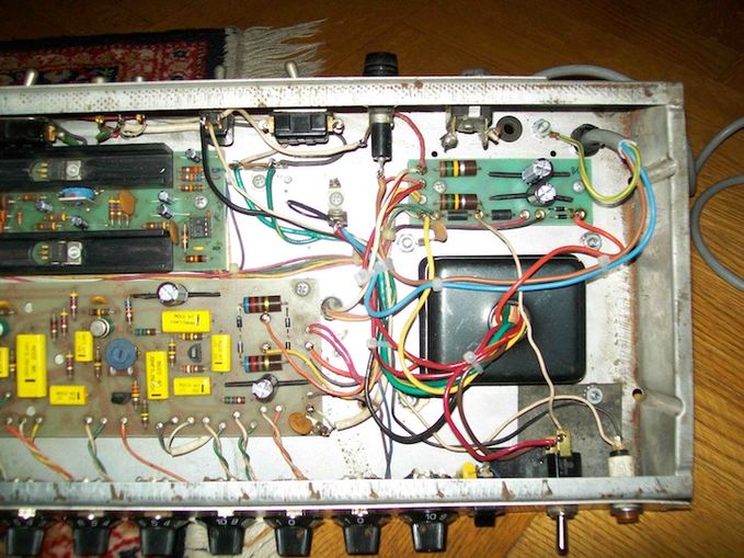
Hey Mike, I hope the deja vu was for the ground issue and not for having to explain how to post pics to a newbie again  But OK... here is my pic: /MM_NewTransformer_NewGround.jpeg{Mojo Transformer with new ground on rectifier board } | ||
| DT (the_groke) Username: the_groke Registered: 02-2013 |
Oops... backslash! but when I add it with backslash it's still not working... I get this error: Error Formatting Error The formatting code mm_newtransformer_newground.jpeg does not exist or cannot be used in this context. | ||
| Mike Kaus (mm210) Username: mm210 Registered: 05-2006 |
No problems. You can't imagine how many time I screwed up posting pics! | ||
| DT (the_groke) Username: the_groke Registered: 02-2013 |
 | ||
| DT (the_groke) Username: the_groke Registered: 02-2013 |
and here it is in it's "trash score" condition, with clipped off 220V transformer (shorted). 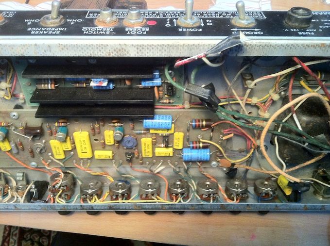 | ||
| Mike Kaus (mm210) Username: mm210 Registered: 05-2006 |
Nicely done and neat. Are those radial caps from the factory or did you put them in? I've just never seen radials in instead of axials in a board confog like that. Just asking> Mike. | ||
| DT (the_groke) Username: the_groke Registered: 02-2013 |
heh... thanks, but the tech is largely responsible for cleaning everthing up - he removed the ground flip switch etc. The caps are Nichicon PW series. A good high quality all around low-impedance cap. Maybe not ideal in audio paths (the nichicon MUSE are better for that), but I've used them in lots of synths and guitar pedals (which is usually what I am playing around with trying to fix), and they've been fine. I just bend the legs to fit and (sometimes) put on shrink tubing. When I recap, I always use axials if I can. I see no point in spending tons of money on radials if I can just bend the legs and put in an 15-50 cent axial (I used them on the bottom too... ). These are way better quality and way cheaper than the no-name or old dead stock axial stuff on the market - and they have higher temperature ratings. Of course, sometimes they won't fit quite right, and some people might want the board to maintain the classic look, which I guess I can understand. | ||
| DT (the_groke) Username: the_groke Registered: 02-2013 |
Here's a pic of the bottom. Same approach, with some plastic pull ties to keep everything safe. Two around the cardboard bottom and one around the two cap bodies. 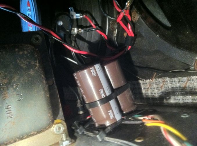 | ||
| Mike Kaus (mm210) Username: mm210 Registered: 05-2006 |
Now THAT'S a little spooky looking! Hope you don't have to get behind there and wiggle any speaker wires! You have to make some things work but I would put some kind of shield around it to keep fingers from touching the wrong things. Just my 2c's worth. Mike. | ||
| DT (the_groke) Username: the_groke Registered: 02-2013 |
Not ideal, I'll admit, but there is actually less exposed wire than on the original. You can't see, but I have tubing on the leads. | ||
| Mike Kaus (mm210) Username: mm210 Registered: 05-2006 |
That's good. I know sometimes you have to do what's neccessary. Yesterday had to build a cap pack to replace the cap CAN in one of my pieces of test gear(my Eico signal tracer-love that old thing). Anyway, 20-20-10-10@ 450 volts. Have axials in stock and unwilling to spend $30.00 for ONE cap can. It's not "ideal" either but it's test gear, not an amp bouncing all over hell in the back of a truck. Gawd bless hot glue and zip ties! I also find it amazing in old test gear how MANY things that they can hang off of ONE point. There are no less than three components being tagged off of EACH contact on the cap can. Flying leads everywhere! I don't honestly know how they kept them straight in a production setting. Mike. | ||
| DT (the_groke) Username: the_groke Registered: 02-2013 |
I should put something over the solder joints though... Even on the original set up, it's an accident waiting to happen - it's right near the reverb send/return. Which Eico? The tube one? I have a Model 150 (the solid state one), that was heavily modded. I keep meaning to bring it back to normal so I can use it. Did you cut the can open and re-stuff, or just replace it with the cap pack? I've always wanted to try the former. I think I would need a dremmel to cut open cleanly though. | ||
| Mike Kaus (mm210) Username: mm210 Registered: 05-2006 |
I didn't cut it open but they wouldn't fit anyway. I STARTED to open it but backed off. It's a tube version-model 147. I actually used it one time to record a guitar part on a track I was doing. Wanted that little speaker driven like hell sound. don't rememeber what song it was. I remember it being PERFECT for the track. The Eico, I hot glued the pack together and then, after getting all 500(just kidding) connections done as much as I could, hot glued THAT to the back of the chassis. Plenty of room in there. HAd to extend a few leads from the resisitors that were taggged on but it worked out well. It wasn't broke, just doing it because that can is at least 40 yrs old and a accident waiting to happen! | ||
| Ed Goforth (ed_goforth) Username: ed_goforth Registered: 06-2006 |
I can not see the op-amp chip on the Solid state driver board with the big heat sink, but some have been spotted with other than the 1458 chip they came with. In the service bulletin it says use the 1458 only in this circuit here! I have had some come my way and it causes problems if it's anything other than a 1458. Plus the 1458 actually sounds best in these, some think upgrading to a higher performance chip would be a good thing, but it can sound harsh and not perform the way it was designed to. They always sound better with a 1458 in the driver. A 4558, 353 etc. has been discouraged to use. Just a heads up :^) If a driver transistor goes bad, it will hum badly, a filter cap too, even a faulty chip! Check them if you still have issues. |
Tue, 03/25/2014 - 09:53
#1