| Author | Message | ||
| Vic Lund (grounded) Username: grounded Registered: 05-2012 |
I bought it used in '82. I own 8 guitar amps. Fenders, Marshalls and, some unique pawn-shop prizes that were cheap and sounded 'cool'. But this is my #1 and has been since I bought it. I have played Hundreds of gigs with it and it has always brought home the bacon. I have changed tubes in it twice. One of those times (1993) was from a melt-down. The Tech (who is no longer with us and I MISS HIM) had to replace one of the Output Tube Sockets. Since then, it has been a faithful, trouble-free, tone-to-die-for, Companion. It looks a little worse-for-wear, but I have gone to great lengths to keep it from any serious harm. Now it makes occasional sputtering noises. This noise is always the same volume regardless of where the Master volume is. Channel volume has no effect on it either. Everything else still worked great but, it won't be turned on again until I know its safe to do so. I have been told it could be the Electrolytic Capacitors in the output section. To my knowledge they are still the Factory Caps from the 70's. It hasn't been turned-on since it started making this noise. I would like to change these out myself. The guys around these parts that still know what a tube is just don't have the passion or my confidence. If anybody from the Music Man brain trust have any tips, I would be much obliged. I am good with a soldering Iron, know how to read a Multi-Meter, and I know that those Caps carry LETHAL doses of DC Current. I work in the supply side of the Electrical business. I have good access to whatever tools I need. I just bought an AMP-HEAD DBTP-MPD Dual Bias Tester for the EL34's and some 1,000 volt insulated screwdrivers and pliers. The Bias tester is supposed to let me switch between tubes to measure MA and Plate Voltage. Like I said, any help would be appreciated. Thanks -grounded | ||
| Mike Kaus (mm210) Username: mm210 Registered: 05-2006 |
OK, if your're familiar with high voltage amps, I'll skip the stuff about being careful with high voltages. Drain the caps with a 1K-10K 1 watt resistor to ground and then check the caps to grounds after drained. Replace caps with appropriate replacements. I have used every brand out there other than F+T and that's just because they're REALLY high and not redily available. I use everything from Weber stuff to Nichion to Sprague and Illinois. I realll have had NO reall trouble with any of them, but I know some people have a boner for Illinois caps. I don't. I have them in stock for repairs and have them in my personal amp and have had no problems. I do know there was a batch of Weber caps that had some sub-standard small caps subbed INSIDE the larger cap cans but I think THAT has been taken care of. I have been doing this for a LOT of years and I STILL mark EVERY amp I work on as to the orientation of the caps with a sharpie or equivilent. No senese in being stupid. When I work on a customer amp, I even stake PICTURES of the amp inside and out to prove not only what I have done but as a reference to before the work. You'd be surprised what musicians will acuse you of(and I AM one!). The photos wil also give you a record of how it was before. Now, the caps will be marked but you should LOOK at the caps themselves because I have SEEN caps that were marked wrong. Look for the insulator in the + end. It will look like a rubber washer on the end. The - end will be bare metal. Make SURE that you replace the caps on the bias supply board. That's the small board in the corner. By the way, does this amp have a 12ax7 tube in it or a SS driver? Either way, the board in the middle rear will have electrolytics on it also. The question will come up about removing the main board to replace any electrolytics on IT. I DON'T. You will get different opinions on this and I will just say that I have replaced them for YEARS and don't do it. It's a PITA. I clip the caps as close to the body as I can(marking them beforehand) and then kind of tying the leads of the caps to the flying lead from the board. I make sure that I clean the leads before tying so that they will solder easily. Now I solder fast and have been doing it for 8000 years so I don't get the lead that hot that I have to worry about softening the solder on the other side of the board but you MIGHT want to heat sink the lead on the top side of the board if you concerned. A pair of forceps works good for that. NOW comes the fun part. MOST of the snap crackle pop noises that I have run into over the years has been from dirty tube sockets or cold solder joint with a few cracked resistors on the sockets. MOSTLY, cleaning and retensioning sockets does wonders. I won't go into re-tensions sockets-google retension tubes sockets and you will come up with 1000 hits on that at least. I use Caig de-oxit or something like that and an old tube to clean them and THEN re-tension them, if you can. Some of the new cheap a$$ chines ceramic sockets, you can't get to them without either taking them out and some you're just screwed and have to replace them. Cheap junk. Anyway, clean and re-tension, make sure you remove the resitor that you used to drain the caps and fire the mutha up. If you have the 12ax7, you can set the idle current to around 22-23mA per tube and be confident that it will be cool last. Todays tubes really are a crap shoot. If you have the SS driver, follow the instructions on the pages here pertaining to driver measured across the bias RESISTORS. In THAT case, your bias gizmo is worthless because those SS driver amps are cathode driven and the limiter is in the drive side. Anyway, long winded as usual but if you have questions, I or the other great people here will be GLAD to help. Mike. | ||
| Vic Lund (grounded) Username: grounded Registered: 05-2012 |
Thanks Mike. I really appreciate the good advice. 12xa7 driver. It and, the EL34's are in great shape. I have a friend that is in to HAM radio. Loves the Tube stuff. He has an old-time, Technicians, Tube tester. Not one of those ones that says Good/Bad. He had me scrape every pin on every tube with an exacto knife, then hit it with a shot of Deoxit D5. Now that you mention it, there are several Sockets that are loose. Sounds like I need to get on that pretty quick. I have built a jig and screwed the chassis to it. Next-up, I'll post a couple of pics. I take a LOT of pictures when I do projects. I have to put that thing back together, I want to make sure it looks something like it did before I took it apart. I still have a couple of questions if you don't mind. Thanks again - Grounded | ||
| Vic Lund (grounded) Username: grounded Registered: 05-2012 |
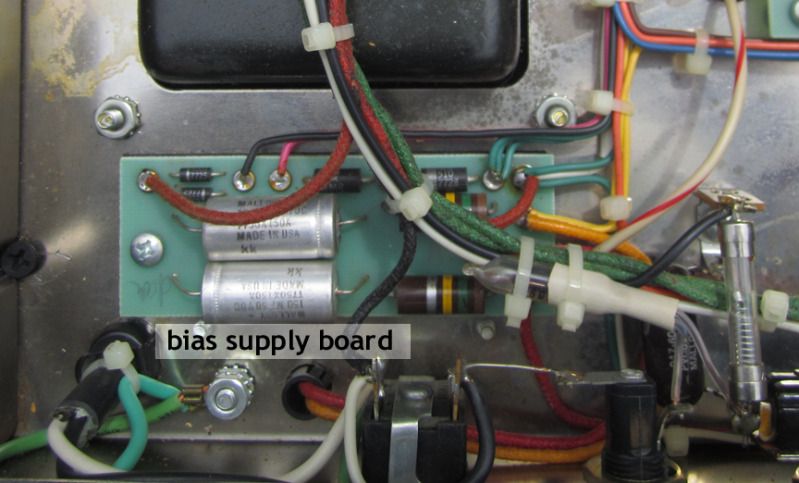
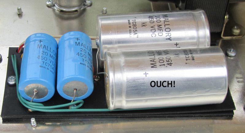
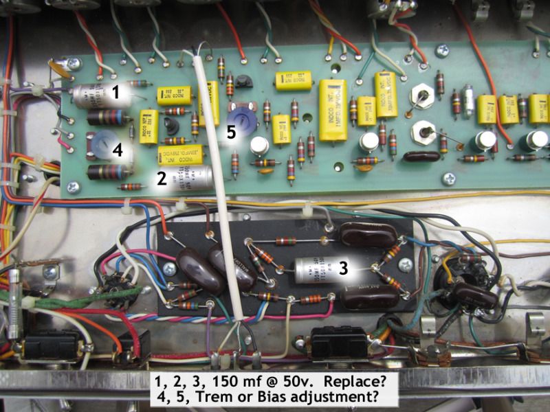
Hey Mike, I took some pics, your opinion please: 1)I'm assuming this is the Bias Board? http://i26.photobucket.com/albums/c113/v ikrude/BiasSupplyBoard1.jpg 2) These are the Filter Caps? http://i26.photobucket.com/albums/c113/v ikrude/FilterCaps1.jpg 3) 3 more Eletrolytics and Two different Trim pots. As I understand it, one is for the Trem controls, the other, the Bias adjustment on one of the EL34's. Should I replace three Caps too? Which trim control is which? http://i26.photobucket.com/albums/c113/v ikrude/CapandBiasID11.jpg Thanks - grounded | ||
| Mike Kaus (mm210) Username: mm210 Registered: 05-2006 |
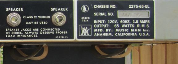
Yes, that's the bias supply board. VERY important that you replace them. Yes, also on the filter caps. I would go ahead and replace ALL those electrolytics, including 1, 2, and 3. They are cheap that small and ALL of them could have dried out. The little pot closes to then end edge is the bias supply pot, the other trem trim. I don't get it when you said "Bias adjustment on one of the EL34's. Control grid voltage is fed to all the power tubes. Alson, I assume that this is an export amp since I see too many fuses for a US bound amp. That one soldered in the PT feed is the giveaway. Also, too many fuse holders! | ||
| Vic Lund (grounded) Username: grounded Registered: 05-2012 |
mm210, thank you once again for your insight. "I don't get it when you said "Bias adjustment on one of the EL34's" That is because I honestly don't know the finer points of Electronic Repair and the Theory behind it. "I assume that this is an export amp since I see too many fuses for a US bound amp." http://i26.photobucket.com/albums/c113/v ikrude/MadeinUSA.jpg I have no idea what, where or, how, before I bought it. It came with a factory installed, NEMA 5-15P for the AC Power. As for the Soldering, is my 25 watt Hakko Pencil Considered adequate for the task? Is there a Grade of Solder that you recommend? ~ Grounded | ||
| Mike Kaus (mm210) Username: mm210 Registered: 05-2006 |
Wasn't trying to insult you. Just with the large number of folks here that are from various countries, I sometimes mis-understand some people due to the language variances and I didn't want to mis-guide you. It's just the only transformer schematics that I have seen with fuses on the PT are exports. That doesn't mean they don't exist. Who knows, you may have something special! 25 watt is plenty for the circuit board and the like. I use a 15-30 watt for 99.9% of the stuff I do. Only use the bigger guns for power cords and the 1000 watt monster for soldering chassis connection-few and far between! Solder, there is no substitute for good old Kester but honestly, I have several rolls of good old rat shack solder that I love. The radio shack stuff is also easily accessible. I keep several sizes here but for most amp work, the stuff that is around .030 is good. Rosin core, of course. I keep every size from the hair fine stuff for pc boards to large enough to solder 10 gauge wire. never know WHAT you'll run into. Mike. | ||
| Vic Lund (grounded) Username: grounded Registered: 05-2012 |
No offense taken. This is all an age of discovery (about my amp) for me. Things I never knew about Music Man amps!  All I've known about this old hoss is that she has brought home the Bacon too many times to count. '93 was the last repair. It hasn't been opened-up since then until just recently. I'll grab some Caps and get to it. | ||
| Mike Kaus (mm210) Username: mm210 Registered: 05-2006 |
Any help needed, let me or us know. Like I said, I never pull the mail board out to replace those two or three caps-too big of a pain in the tush. Scrape clean, tie them in a knot and solder. Never had ONE come back yet. I would kind of like to know more about that amp since it has all the extra fuses like an export amp. Maybe if Lars pops in he can shed light on it. He's SEEN the export amps and I haven't seen one with xtra fuses on the PT. | ||
| Lars Verholt (lmv) Username: lmv Registered: 11-2009 |
Mike, I'm sorta thinking this is an old version of the Domestic issue sixty-five amp. The old EX amps (UK, most of Europe) didn't have an extra fuse but did have a two pole power switch. The EX-SC (for Scandinavia) had all those extra fuses in on the secondary side of the PT (plus the dual pole power switch of course). These fuses (four in total) were mounted on a plastic holder. Either way, as long as it works it's no big deal. An original MM amp would very likely benefit from getting new electrolytic caps. Also - check (or replace) the bleeder resistors on the main filter caps (150k 2W) and the 620 ohm 2W low voltage supply resistors. Other common components to replace are the HV clamp caps on the power tubes and zener diodes in the +- 16V supply (bump up wattage to 2 watts). The latter parts are stuff you would replace for a customer as a preventive measure - but for your own amp, you may leave them alone until you suspect problems. A couple of basic tips: 1. Don't work on this if you are tired or otherwise not focused 2. Don't work on this if not sober (see above) 3. Have sufficient lighting to work by 4. BEFORE switching on the power check for stray solder 'blobs' and other lost bits of debris that may have become stuck inside the amp chassis Best of luck! -Lars Verholt www.captain-foldback.com | ||
| Vic Lund (grounded) Username: grounded Registered: 05-2012 |
Thanks Lars. I have been building up to this since late January. I agree with tips: 1, 2, 3, and, 4. One can't let emotion get in the way of good judgement. Electricity doesn't care how I feel, it will kill me if I don't take every precaution. I'm not in a hurry. I have other Amps I use. When I feel like I've had enough, I quit for the day. I built a wooden platform for it. It is bolted-down on 4 places and allows access from any angle. Even upside-down. I'll keep you guys posted. | ||
| Vic Lund (grounded) Username: grounded Registered: 05-2012 |
From what I can see, I need: 5) 150mf 50vdc 2) 20mf 450vdc 2) 100mfd 450vdc Everywhere I go I see Close, but not exactly what I have in there. I get a lot of "You'll never know the difference" from people who don't play. Is there a rule of thumb for how close a Cap can be? Should they all be Axial Lead? Should I stick to Guns and hold out for exactly what came stock? Thanks grounded | ||
| Lars Verholt (lmv) Username: lmv Registered: 11-2009 |
From www.mouser.com Part no 75-TVA1718-E3 - 100uF/450V Sprauge Atom 75-TVA1709 - 20uF/450V Sprague Atom TVA1311-E3 - 150uF/50V Sprague Atom Done -Lars Verholt | ||
| Mike Kaus (mm210) Username: mm210 Registered: 05-2006 |
Hmmmm. Nothing to do with this thread other than I check this site 3-4 times a day and I didn't see Vic's last post until tonight(5-3---7:30 pm). Wondering why i didn't see new posts all day today until THIS late. HMMMMMMMM? | ||
| Lars Verholt (lmv) Username: lmv Registered: 11-2009 |
You could be the victim of transparent caching - something some ISP's will engage in to save on bandwidth at peak periods. That or your local browser cache was playing tricks on you. As long as you're back on the same time speeed as the rest of us now.... -Lars Verholt | ||
| Mike Kaus (mm210) Username: mm210 Registered: 05-2006 |
Good info on the amp Lars. I have NOT worked on ANY export animals so I'm not much help. I have never seen a MM with a fuse soldered in though. Looks nice and factory-ish, just wierd. Two other fuse holders there too. I kind of thought they were all on one fuse board but guess THAT'S wrong. I flush my stuff every couple of hours to keep wierd stuff from caching happening here so I'm going to ASSUME (and we all know what that does) that it's on the ISP side. | ||
| T.E. Price (uposb4) Username: uposb4 Registered: 05-2006 |
Vic, How's the cap job coming along? Keep us posted. | ||
| Vic Lund (grounded) Username: grounded Registered: 05-2012 |
Hey everybody, after all this time I finally soldered-in all the new Caps. Back in July, I bought an AMP-HEAD Dual Bias Tester. It has tow Socket Adapters that go in to the Tube Sockets while the Tubes plug in to them. Two separate leads go to my Multi-Tester. It has two switches on it. Switch one, One Tube/ Tube Two. Switch Two, DC Voltage/Milliamps. What are the numbers I'm looking for? 22 - 24 MA? How close should one tube be to the other? | ||
| Vic Lund (grounded) Username: grounded Registered: 05-2012 |
I will have it plugged-in to an 8ohm cab. Do I want this on the HIGH Power setting? Where should the Volume and Tone controls be? | ||
| Mike Kaus (mm210) Username: mm210 Registered: 05-2006 |
High setting, volume on "0", tone, don't care. MAke sure you are setting switch to 8 ohms. 22-23 is where I'd be. | ||
| Vic Lund (grounded) Username: grounded Registered: 05-2012 |
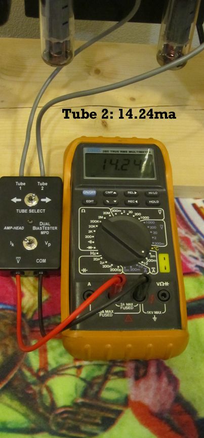
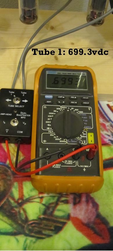
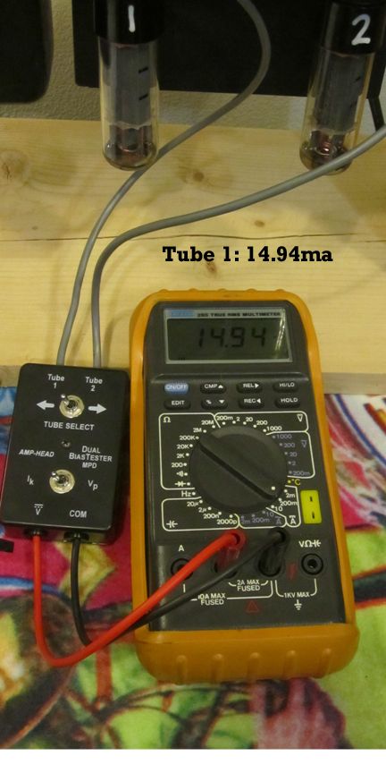
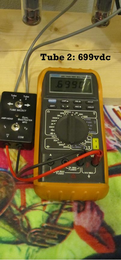
I replaced the Caps, and the Bias is all over the place. Tube 1 (Closest to the middle) reads about 22+ ma, Tube 2 reads 14ma. Voltage is at about 710VDC. Looks like I need to replace the the bleeder resistors on the main filter caps (150k 2W, the 620 ohm 2W low voltage supply resistors, the HV clamp caps on the power tubes and Zener diodes in the +- 16V supply (bump up wattage to 2 watts)like Lmv had suggested. | ||
| Mike Kaus (mm210) Username: mm210 Registered: 05-2006 |
Good suggestions on the resistors. Are you sure that the tubes themselves are matched? Are they new? Old? What brand? Did you check the bias BEFORE you replaced the caps? You're SURE that the caps are oriented properly? Just asking for safety's sake. Mike. | ||
| Vic Lund (grounded) Username: grounded Registered: 05-2012 |
The Tubes are old. I have no idea how Matched they are. The last time they were changed was 1993. Had a Power Tube Melt-down. Didn't think to see what was in there before they were replaced. What was there was replaced with SOVTEK EL34G's. They look great. No signs of Heat discoloration, flaking on the inside, corrosion, cracking ... But the Tube on the inside is burning redder and, drawing twice the current of the outside Tube. I'll post a couple of pics in my next post. In '93, the Amp started to make a loud humming sound that was UN-controllable by the Volume pot. The 'inside' tube (closest to the Transformer) burned so bright and so hot, the tube socket had to be replaced. It has worked with no problems ever since. This Amp has been soooo reliable. I regret, I did not have anything to test the Tubes with the before I changed-out all of the Electrolytic Caps. As far as orientation (of the Caps) goes, I took dozens of pictures and marked + next to every Cap before I removed anything. I double checked it a couple of times before I plugged it in last night. | ||
| Mike Kaus (mm210) Username: mm210 Registered: 05-2006 |
With 12ax7, sounds like you are loosing bias on that tube or it it unusually low on that socket. Measure the voltage on pin 5 and see what it is and if it's the same on both sockets. Tubes OUT for that. If they are the same, then MAYBE that socket has a bad contact with THAT pin. Re-tension and clean. If they are different, then you will have to go back through and see why the voltage is less on that pin. Remember, the MORE negative voltage, the less current it will conduct. Also, what happens if you swap the tubes? Does the same socket get red or does it follow the tube? Mike. | ||
| Vic Lund (grounded) Username: grounded Registered: 05-2012 |
Which pin is pin 5? Looking straight down from the top of the chassis, like it would be if it was in its cab playing at a gig, I see pin 8. Do I count counter-clockwise to 5? These pics show the results of tonight's test. You can see the Vdc and ma readings as I saw them. Please let me know if I am over-looking anything. http://i26.photobucket.com/albums/c113/v ikrude/T21494ma_zps7f657ed9.jpg http://i26.photobucket.com/albums/c113/v ikrude/T1699vdc_zpsf1f43906.jpg http://i26.photobucket.com/albums/c113/v ikrude/T11494ma_zps19658bf3.jpg http://i26.photobucket.com/albums/c113/v ikrude/T2699vdc_zpsc6221ad5.jpg | ||
| Vic Lund (grounded) Username: grounded Registered: 05-2012 |
Those settings were with the Trim-pot all the way open. It appears to raise and lower the ma to both Tubes at the same time. Is that correct? Thanks. | ||
| Vic Lund (grounded) Username: grounded Registered: 05-2012 |
Mike, when I test for that voltage with the "Tubes out", do I remove the 12ax7 too? Thanks | ||
| Mike Kaus (mm210) Username: mm210 Registered: 05-2006 |
OK-12ax7 can be left in. If your bias setting indicate that the bias is 14.xx ma, then it IS receiving the proper amount of control voltage or it wouldn't be tamed down THAT much. Yes, both tubes will adjust at the same time. If you run it with the bias THAT low, do the tubes still red out? It sounds kind of like you had a tube take a crap. I would still check the control VOLTAGE on the sockets and re-tension them. Here's a pic showing the numbering. 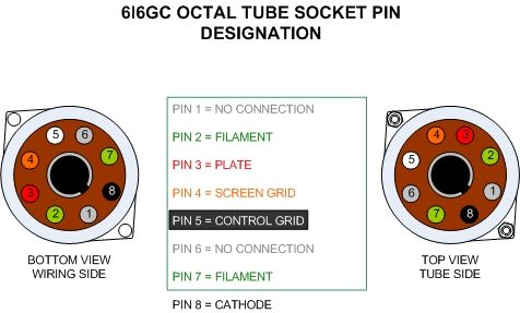 | ||
| Vic Lund (grounded) Username: grounded Registered: 05-2012 |
Pin 5 measures 330vdc on both sockets. | ||
| Mike Kaus (mm210) Username: mm210 Registered: 05-2006 |
That CANNOT be right. It should measure somewhere around -25 to -50 Volts, not positive and NOT that much. Are you SURE you got the right pin? If you look closely, the bottom of the socket SHOULD actually have the numbers on it. | ||
| Vic Lund (grounded) Username: grounded Registered: 05-2012 |
I'll double-check. Could be I set the Multiplier wrong on my Meter. 6L6 and EL34 pin-outs are the same? But you point is I should be getting Negative Voltage readings? | ||
| Vic Lund (grounded) Username: grounded Registered: 05-2012 |
The multiplier was incorrect. They read - 33.12vdc | ||
| Mike Kaus (mm210) Username: mm210 Registered: 05-2006 |
That's more like it! Ok, if you have constant voltage like that on both pins but one tube is redplating, either it's tension on THAT pin socket or that tube is junk. Just my 2c's worth. | ||
| Vic Lund (grounded) Username: grounded Registered: 05-2012 |
I think it was a bad tube. I went to the only person around these parts that I feel I can trust and bought a pair of el34's. I've had them in the amp and running for about 5 hours with no ill effects. The loud Hummm is gone. Reminds me of how it used to sound. So we'll see what we see. I'm planning on taking it to practice Thursday night. Haven't told a soul, they will freak-out when they see it. Mike and Lars, can't thank you enough for the input and insight on this project. Your help has been greatly appreciated. Life is short, PLAY LOUD! See you 'round the Clubs Vic | ||
| Mike Kaus (mm210) Username: mm210 Registered: 05-2006 |
Good luck. Let us know. Mike. |
Tue, 03/25/2014 - 09:53
#1