| Author | Message | ||
| Richard Forrester |
is there anybody out there that can do this mod. I have a very specific tone(Fulldrive 2 with this amp is awesome), but i need a volume pedal that does not effect the tone. IF you can, please help me find someone that can do this mod. pandiatonicism@hotmail.com | ||
| Clayton Choate |
My 210HD 130 has an effects loop and I am convinced this has affected the quality of the amps sound. I'd like to find someone who can remove it and get me back to original specs. The loop was there when I bought the amp so I don't know what an unaltered amp would sound like. Be Careful! | ||
| Clayton Choate |
Oops1 My amp is a 212 HD not a 210. Sorry! | ||
| c. |
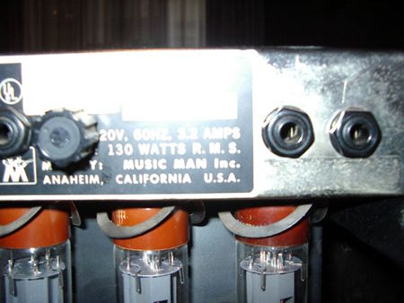 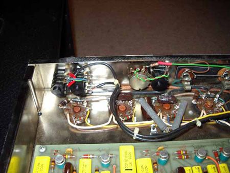 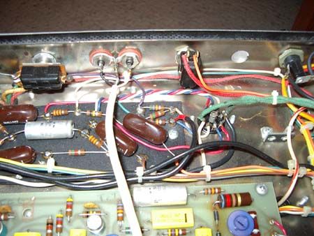 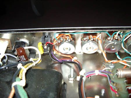 these pics sort of show where the loop was taken from, there is also a line out with level - so it can be done | ||
| c. |
sorry steve - you can edit the first attempt! as well as this, BTW looks like we BOTH lucked out on the 130 head on ebay! he he. | ||
| michael kaus |
If you want, email me and I'll send you a scan of an original schem from music man that is hand altered by one of the r+d guys in 77 or so that shows where they put in an effects send and return. It also shows the mods thay did to claptons amps when he used them. Rather a prized little piece of history! Mike. | ||
| admin |
From the photos, it appears that the Send & Return Jacks are just in series with the feed to the Master Volume Control. I can't see enough detail to know for sure, but it probably is easy to undo. As long as the switching contacts on the jacks are in good shape it and you don't use the jacks it doesn't look like it should effect the sound too badly. Just make sure the switching contacts on the jack are well tensioned and clean if you leave them intact. Steve | ||
| Ed Goforth (ed_goforth) Username: ed_goforth Registered: 06-2006 |
I have tried this Clapton Loop, but it overdrives the effects somewhat. I would rewire the send side to the wiper caps output and return where the other end of the .047 uf wiper cap comes back to the circuit. It sounds way better. Also I noticed that the Clapton loop changes the tone and gain of the amp. Rewiring it to the above would keep the tone stock when not used, and does not change gain when when used. The tone may vary depending on the effects used. | ||
| Ed Goforth (ed_goforth) Username: ed_goforth Registered: 06-2006 |
the wiper I mentioned is the middle lug on the master volume pot. In case anyone did not know :^) Ed | ||
| Phil Andrews (phil_andrews) Username: phil_andrews Registered: 03-2007 |
So to install a post-Clapton efx loop, are you saying to break the circuit *after* the cap that follows the master gain, or to wire it across that cap? I've been learning as I go here, resurrecting an HD-130 that someone gave me recently (which would be impossible, for me at least, without this excellent forum). | ||
| Ed Goforth (ed_goforth) Username: ed_goforth Registered: 06-2006 |
The .047uf cap that comes off the wiper of the master volume, take the output side of the cap as your send --[]---send break, then your return will come back at this point. I use a closed stereo jack, that when the loop is not being used, the signal path is stock, when the path is interupted and effects are inserted here, your master volume also acts as a master effects send control to your effects and you can match up the signal levels better. The Clapton mod breaks the signal just as the signal hits the master volume and so your effects are going to get a big signal no matter what, especially if you use the amps gain set high. So having the send after the master wiper cap, you solve the overloading problem and can get more amp overdrive into your effects without ruining your tone. I hope that helps. Be sure the cap is before the send jack or you will be sending high voltage into your effects, :/ The effects should have a capacitor coupling its output, so I don't think you will need another cap there. I am currently modding a HD-130 now with this loop and when I am finished I will post more on any changes if there are any. Ed | ||
| Phil Andrews (phil_andrews) Username: phil_andrews Registered: 03-2007 |
Thanks for clarifying. I was thinking of doing the same thing, using just one TRS jack like a mixer insert. It could go in place of the second speaker jack so I don't have to drill any holes. I'm sure I'll have more questions about something else, though... | ||
| Ed Goforth (ed_goforth) Username: ed_goforth Registered: 06-2006 |
Hi Phil, any questions are welcome. You can email directly if you like goforthsound@yahoo.com and I am sure many here can answer as well. I hooked up the loop today and inserted the effects. they work great! What will make them sound even better is having an outboard tube buffered loop, it really warms up the sounds and you can control the overall master volume by the effects return, allowing the amps master to be turned up more, less buzz, but anything over 3-4 with the pregain maxxed would probably overload the effects without a buffered loop. | ||
| Ed Goforth (ed_goforth) Username: ed_goforth Registered: 06-2006 |
BTW, there should be a .1uf/600vdc or better at the send lugs of the stereo jack and replace the .047uf on the board where the cap comes off the master volume wiper with a .1uf there also. So you have a .1uf send and a .1uf return, to keep any dc voltages from entering the signal. The reason for 2 .1uf caps in place of the (1) .047uf, is for 1. is your are filtering out any dc voltages (send/return)and the .1uf value is because having them in series with the effects out of the loop, .1uf + .1uf = .047, so the low end stays intact and = the stock value in circuit. If you were to use 2-,047uf caps it would =.022uf. Theory in capacitance: Basically values in series = 1/2 their added value. 2- caps in parallel = double their value. Resistors are opposite of this, 2 resistors in series of the same value = double their individual value, 2 of the same resistors in parallel = 1/2 their value. Confused yet? :P You probably already know this stuff, but if not, maybe it will help you or others to understand why I did it that way and it worked great! Ed | ||
| Phil Andrews (phil_andrews) Username: phil_andrews Registered: 03-2007 |
I wouldn't have thought of that myself, but I do get the concept. Looking at the layout, it might be wise to shield the signal leads, too. While I'm in there, would it be a good idea to replace all the big brown caps on the phase inverter board? I've already replaced every electrolytic in the amp (and some other stuff), but no other caps. Opinions seem to vary about what can go bad. | ||
| Mike Kaus (mm210) Username: mm210 Registered: 05-2006 |
HMMM? Tried to post a reply and it went to cyber space. Anyway, don't replace anything other than the electrolytics unless you have a particular problem. IF your amp has a "death" cap across the power input, I's ace it out or at least replace IT. Mike. | ||
| Phil Andrews (phil_andrews) Username: phil_andrews Registered: 03-2007 |
Thaks, Mike. If it ain't broke... The cathode resistors on top of the sockets had drifted way out of spec, and didn't match eachother, so I changed those. I also replaced a transistor for the vibrato (just wiggling the trimpot hadn't helped), and that works now. (Good, because I actually use that effect.) Also the diodes in the bias supply circuit looked like they'd been through a fire, and someone in these forums mentioned it, so those are gone too. But I'll stop now. | ||
| Mike Kaus (mm210) Username: mm210 Registered: 05-2006 |
THe ONE thing that I always do is replace the bias feed resistors balanced over the sockets-I believe that they are 1.5k. The only reason that I do this is due to the heat. THere are caps over the sockets to that might be a good idea to replace also, just due to the heat. While you're at it, just replace the diodes over the sockets. I assume that yyou changed the bias supply caps? | ||
| Phil Andrews (phil_andrews) Username: phil_andrews Registered: 03-2007 |
Those resistors read fine on a meter, but I might as well while it's opened up. What type are the diodes? the only part of the schematic I can make out is 5k volts. Yes, I did replace the caps in the bias supply. Contrary to popular belief I found it pretty easy to lift the main board and work under it. | ||
| Mike Kaus (mm210) Username: mm210 Registered: 05-2006 |
THey look like 4007's but I'm not really sure. I put in 3a diodes just because I have a boat load of them too. I just usually replace ANYTHING that is heat affected. THe 470 ohm screeners on Fender amps are the FIRST to go. THey are bad about taking a ------. | ||
| Phil Andrews (phil_andrews) Username: phil_andrews Registered: 03-2007 |
Success! The hard part was finding a double-shorting jack for my new effects loop. Also, at first it produced no sound at all; I was baffled for some time until I realized I hadn't turned on the standby... A couple of issues remain, however. 1. Low output. The volume drops significantly with the loop plugged in. For now the solution is to crank the level trimmers on the effects. Is there a better way? If I tap the signal before the master volume, a la Clapton mod, would that degrade tone? 2. Stray voltage. If I press the chassis with my thumb while unplugging the insert, I get a mild shock. (amp unplugged, electrolytics drained). I'm guessing it's coupling capacitor discharging somehow when the jack shorts? Should I be concerned? 3. Speaking of voltage, is the "death cap" the one between the ground switch and the chassis? Is there any reason I shouldn't disconnect the switch and tape off the leads? | ||
| Phil Andrews (phil_andrews) Username: phil_andrews Registered: 03-2007 |
AARGH! So I put the chassis back together, plugged in, played around for a while, and it sounded great. But when I turned it up really loud, a bad crackling noise started to happen -- like popcorn popping. It now occues at all levels, but it's much louder on the second channel, and it's picked up by the reverb. However, it's audible on the first channel too, and less so with both channels on zero and just the master turned up. Any thoughts from the MM brain trust? My effects loop? Something in channel 2? Something else? I'm clueless about this one. | ||
| Mike Kaus (mm210) Username: mm210 Registered: 05-2006 |
I'm afraid you're going to have to scope it to find this one. Run a 1k signal in the fornt end and just start tracing it through until you see the "pops" in the signal chain. It might be overloading the IC's though. I haven't really been following this but it sounds like maybe you need to un-do your stuff, go back to the beginning and start doing ONE thing ata time to see what changes the signal path. I know it's more work but it is sometimes the best. Do the mods, just one at a time/ | ||
| Phil Andrews (phil_andrews) Username: phil_andrews Registered: 03-2007 |
That's what I was afraid of. I do test as I go, and the only things changed since the last test are the screen resistors and the efx loop, so that's easy. I have a bad feeling it's something urelated, somewhere else. Thanks for your help. | ||
| Dustin Simons (dustin_the_wind) Username: dustin_the_wind Registered: 10-2006 |
If the screen resistors were installed improperly or have a bad connection, that could account for the crackling noise, but I'm sure you already checked those (it sounds like you know what you're doing!). Otherwise you just have to pull out your schematic and start going through to find it. Dustin | ||
| Phil Andrews (phil_andrews) Username: phil_andrews Registered: 03-2007 |
Found it, I think. One of the IC's on channel 2 is bad, and freaks out when you hit it with too much current. For now I've borrowed one from the reverb while I read up on possible replacements. Thanks all for your help. |
Tue, 03/25/2014 - 09:48
#1