| Author | Message | ||
Stuart Clancy (maytag) Username: maytag Registered: 03-2013 |
The switch on my amp was frozen in the low "on" position. I purchased a new DPDT unit and wired it the same as the former unit--black and white wires to lower right lug, cap to lower right and middle right, yellow with black stripe wire to upper right. Now the power is on in all three positions,same intensity. Anyone have a diagram? Thanks. | ||
Lars Verholt (lmv) Username: lmv Registered: 11-2009 |
Hi Stuart, the diagrams are found on this forum's parent website. There are two versions of the 2275/2475-65 schematic. From your description it sounds like you have the older version of the two with the 12AX7 phase splitter tube and the hi/lo switching on the primary side of the power transformer. Hope this helps, Lars Verholt www.captain-foldback.com | ||
Mike Kaus (mm210) Username: mm210 Registered: 05-2006 |
The older versions were SPDT so I'm confused. Why DPDT? Here's a pic of a switch with the 12ax7PI. 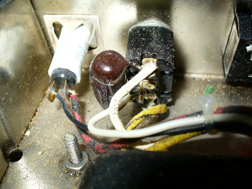 | ||
Stuart Clancy (maytag) Username: maytag Registered: 03-2013 |
Mike, Perhaps the broken switch wasn't the original, hence the DPDT which I copied. Are there only three lugs in your picture--should the black go to the middle? Thanks | ||
Mike Kaus (mm210) Username: mm210 Registered: 05-2006 |
Actually, the black is the supply to the PT,the white, goes to the switch. The different lugs of the PT are the white cloth and the yellow w/black stripe. If you had the BLACK lead from the transformer going to the switch, I don't know WHAT the hell the PO did in the past. You need to have the two different taps going to the PS trannsformer on the opposite sides of the power switch, and the cap across the two legs of the transformer. If you have A DPDT switch,, I have NO clue what they did. Pic maybe of the whole PS area would help and maybe we can figure out what the PI did. Mike (Message edited by usermod1 on April 02, 2013) |